Using Buttons and Switches with an Arduino
Welcome to the fourth instalment of the working with Arduino series! So far we have covered everything from blinky lights, to calculating resistors, to working with graphic displays!
The majority of these have been output based components (what you see). In this article, we will cover input based sensors. The information here can be scaled up for almost all input devices used on an Arduino.
Working with Buttons
Symbol
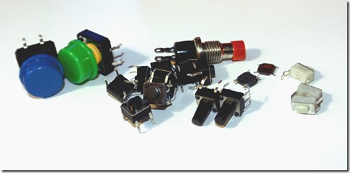
Here is the symbol for buttons, it looks kind of like a circuit waiting to snap open. These are used typically to monitor a momentary press (although there are toggle on and off buttons). In our case, I’m using a “the button is active as long as you hold it” type. These are good for games, turning on LED’s, or triggering something for a limited time. Using Arduino code, we can extend these to operate like click-on and click-off buttons.
Using Buttons
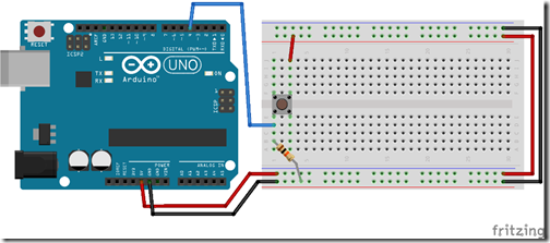
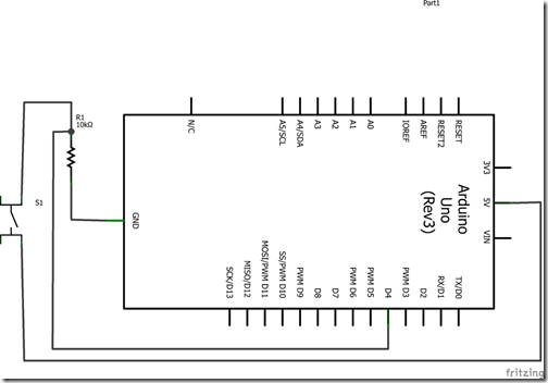
Buttons work by allowing voltage to flow through from + to – while the button is depressed. This will close the circuit, and send 5V of positive down the line. We can use the Arduino to detect this voltage.
For the Arduino, this will need to be fed to a digital input pin.
Reference: We will use digitalRead(PIN); which returns HIGH (getting 5V) or LOW (not getting 5V). And we will also specify pinMode(PIN,OUTPUT); to let the Arduino know we are listening to this pin and not using it for output.
Advanced Topic : Debounce
One of the challenges with buttons is they don’t always work how people think they work. When pressing a button, the voltage change isn’t immediate and definite. That is, it does not immediately begin sending voltage on the new pin and stop sending voltage on the old. Instead, it bounces between the two for a tiny moment and then the change settles in.
For our build, we have a 100ms delay between contact checks. Which means, well, we don’t really care about this. However in more complicated circuitry you may need to build a debounce circuit to smooth this out.
These circuits use a capacitor and resistor to temporarily “hold” onto a charge, and to release it over time. This adds a buffer time in the signal change, preventing the signal from ‘bouncing’ between the two pins.
Working with Tactile Switches (Toggle Switches)
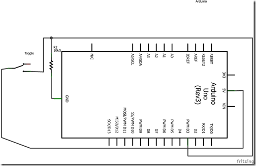
Symbol
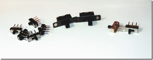
Tactile switches, toggle switches, power buttons… this one has many different names (which makes it actually quite hard to find and purchase sometimes). The symbol looks kind of like a button, but instead of having only one possible outcome – they have two!
Using Toggle Switches
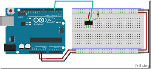
In the examples above, you can see we are almost using the exact same connection method as we did with a button. The middle pin is our input (voltage). When the button is toggled left or right, it switches that voltage to the corresponding pin beside the middle. And some tactile switches allow more than 2 possibilities, making for complex switching modes.
This is great, but what if we don’t want a simple on and off button? What if we want some variance, such as volume knob or dimmer…
Working with Trimpots
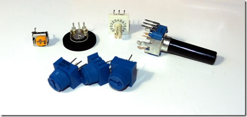
This is where a trimpot (or potentiometer – try saying THAT 10 times fast) comes in handy! Most are big and bulky (such as those used for volume knobs) or they are very tiny and require a screwdriver.
There are some nice thumb-sized trimpots however on Sparkfun. And I’ve shopped around my fair share, they really do have the best ones.
Symbol
You may have noticed that the symbol for trimpots is very close to that of a resistor. The difference is, of course, you can see a third overlapping line – this is for an Analog Input pin in our case.
Using Trimpots
Trimpots are effectively a variable resistor. You turn it more to add or reduce the resistance – increasing the voltage going down the line. This is important for fading things on and off, setting volumes, and fun things of that nature!
Now, be aware, not all trimpots are equal! Some are linear, they go from 0 to 1023 in exact steps. Giving an even voltage gain and loss. However, there are also non-linear trimpots that use exponential resistance. These make less of a difference at one end of the spectrum (such as a volume knob).
Can We Build Something Already?
Ok, we’ve now done a bit of reading about what buttons are and how they work. Lets combine a whole bunch and see some examples.
For those who prefer videos
Example: Using Input Devices without Arduino Code
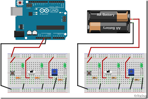
In this example, I’ll show you how to use all 3 without writing a single line of code. We do this by allowing the input items to do what they do best – affect the voltage of something downstream! In this case, some LED’s.
In fact, you can even build this one without an Arduino at all! Just be cautious of your resistances, if you don’t have enough you could burn out an LED or three.
Schematics
Code
[none]
Example: Using Input Devices with Arduino Code
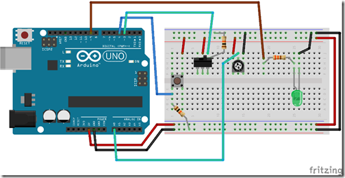
In a more complicated scenario, we might only have one LED. And we might want to apply some logic around it, or later add more advanced features such as noise.
In this case, we are going to make things a bit more complicated:
•The toggle switch will act as a power (on/off switch).
•The button will act as a go or no/go depending on the status of the toggle switch.
•And the trimpot will control the brightness of the LED.
Extra challenge: Can you create the chain above without an Arduino?
Schematics
Code
// Declarations
int LEDPIN = 9;
int BTNPIN = 4;
int TGLPIN = 3;
int TRMPIN = 0;

void setup() {
  // Output
  pinMode(LEDPIN,OUTPUT);

  // Digital Input
  pinMode(BTNPIN, INPUT);
  pinMode(TGLPIN, INPUT);

  // Analog Input
  pinMode(TRMPIN, INPUT);

  // Enable Serial.  To read these debug notes press Tools > Serial Monitor and select 19200 on the bottom right!
  Serial.begin(19200);
  Serial.println("Starting.");
}

void loop() {
  // IS power on?
  int tglOn = digitalRead(TGLPIN);
  Serial.println("digitalRead Toggle : " + String(tglOn));

  int btnOn = digitalRead(BTNPIN);
  Serial.println("digitalRead Button : " + String(btnOn));

  if (tglOn == HIGH) {
// Power is on
Serial.println("Toggle: On");

if (btnOn == HIGH) {
  Serial.println("Button: On");
  // Power is on, Button is on
  int bright = analogRead(TRMPIN) / 4;
  analogWrite(LEDPIN,bright); // Send the 0-255 to LED that we have on Trimpot
  Serial.println("LED:  " + String(bright));
}
else
{
  // Power is on, but button is off
  analogWrite(LEDPIN,0);
  Serial.println("Button: Off");
  Serial.println("LED:  Off");
}
  }
  else
  {
  analogWrite(LEDPIN,0);
  Serial.println("Toggle: Off");
  Serial.println("LED:  Off");
// Power is off
  }
  delay(100);
}
Get it on github!
Thanks a bunch for reading, and join me next time for more Arduino articles!
