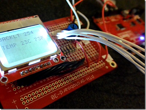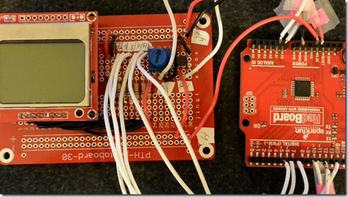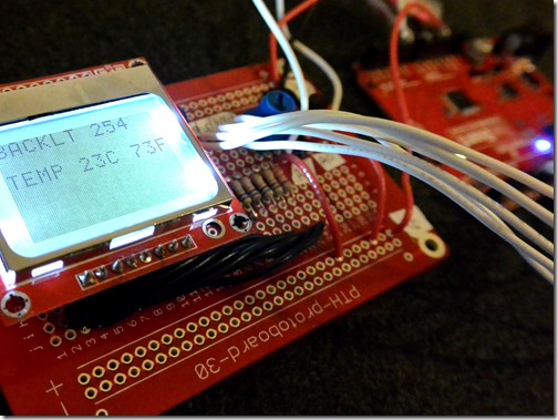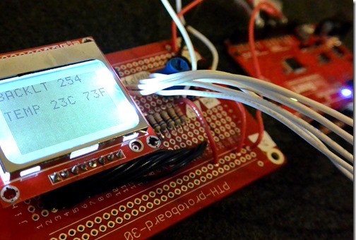
In a previous article, I discussed how to create a Nokia 5110 LCD Display with a TMP36 sensor. Today I will cover this in more detail, with a bit more detail around the how!
Parts
In this article, I’m just going to list the parts I used.
- Mini breadboard – $3 China | $4 Sparkfun / Newark
- Nokia 5110 – $3 China | $10 Sparkfun / Newark
- Arduino Uno – $10 China | $30 Sparkfun / Newark ***
- TMP36 – 5$ China | $1.50 Sparkfun / Newark
- Potentiometer – $1.10 China | $1 Sparkfun / Newark
- 4 x 10kΩ resistor – cheap
- 1 x 330Ω resister – cheap
- 1 x 1kΩ resistor – cheap
Graphic Display Modules versus LEDs
Graphic display modules typically require a few extra steps. They typically need some kind of clock (for timing). Some kind of two way serial communication (this is important as a lot of our tutorials moving forward are going to leverage these serial communication methods) and usually some power and light controls.
What is Serial?
Serial is a communication standard. It allows us to send data on one PIN and receive data on another PIN. Serial requires special timing, which means serial devices also typically need a clock to measure against (and in the world of Arduino, we share our Arduino’s built in clock with devices). If you want to get more technical, this is done by the ATMega328pu module and a 13MHZ crystal.
Hardware versus Software
The last learning section we are going to discuss is hardware serial versus software. Arduino contains several PINs dedicated to hardware serial (0 or receiving or Rx and 1 for sending or Tx). The issue with using the hardware PINs is … well you can only connect one serial device! Not very good if you want to use a wifi module (requires serial) and a display module (requires serial). So instead, we can use a more complicated procedure called Software Serial, which requires some more coding.
On all the tutorials I will only show you software serial.
Diagrams
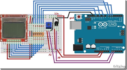
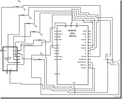
The following diagrams will help you understand how the components are going together.
Inputs
In this article I also include a sensor (TMP36) and an input (Trimpot aka Potentiometer). I won’t go too far into these two, but the important part is they are Analog Inputs. As you may remember from our last tutorial, this means instead of being absolute on or absolute off – they can be ‘in between’.
To do this, they split a voltage between 0v and 5V. They are either linear (smoothly move from 0 to 5V) or they are exponential (more control over one side or the other). This is for things like volume knobs, where slight adjustments at higher levels allow for better control!
Both the TMP36 and Trimpot work as resistors that ‘change’. This is common for analog inputs. So the more you turn the knob, the more the voltage encounters resistance, and the Arduino will detect that change as a voltage.
Assembly:
TMP36
For the temperature sensor, we will use the following formula to determine the temperature:
#define PIN_TMP   0 // analog

// Used to read the voltage of the TMP36
float getVoltage(int pin)
{
  return (analogRead(pin) * 0.004882814);
}
Position the flat-head facing you. Left PIN will go to 5V on Arduino. Middle pin will monitor the change, send this to A0. Right pin will be ground.
Trimpot
For the trimpot adjustment, we will change a variable we are using for contrast.
#define PIN_FADER 1 // analog
#define PIN_LCD   9 // backlight
We will use the top pin as the Trimpot for input. We will use the bottom pin above as the backlight.
Connect the trimpot either direction. Left PIN will go to 5V. Middle pin will be used for sensing and go to A1. Right pin will go to ground.
… notice a commonality with Analog Input devices?
LCD
The LCD us more complicated. We will be adding resistors to all but two of the 8 input pins on the LCD shield.
The LCD requires 3.3V instead of the standard 5V from an Arduino. The simple fix is to simply add resistors to the different PINs.
LCD pin 0 will go to 3.3V LCD pin 1 will go to GND
Above will set our voltages.
LCD pin 2 will go to 1K Resistor and then to PIN 7 LCD pin 2 will go to 10K Resistor and then to PIN 6 LCD pin 2 will go to 10K Resistor and then to PIN 5 LCD pin 2 will go to 10K Resistor and then to PIN 11 LCD pin 2 will go to 10K Resistor and then to PIN 13 LCD pin 2 will go to 330ohm Resistor and then to PIN 19
After the above, we have setup the remaining of the PINs. Compare these to the code below to understand what they do.
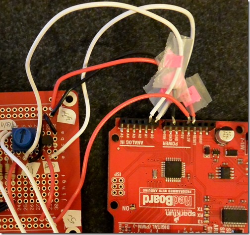
Fully Assembled
Recapping the PIN list
- TMP pin 0 will go to 5V
- TMP pin 1 will go to A0
- TMP pin 2 will go to GND
- Trimpot pin 0 will go to 5V
- Trimpot pin 1 will go to A1
- Trimpot pin 2 will go to GND
- LCD pin 2 will go to 1K Resistor and then to PIN 7
- LCD pin 2 will go to 10K Resistor and then to PIN 6
- LCD pin 2 will go to 10K Resistor and then to PIN 5
- LCD pin 2 will go to 10K Resistor and then to PIN 11
- LCD pin 2 will go to 10K Resistor and then to PIN 13
- LCD pin 2 will go to 330ohm Resistor and then to PIN 19
Video
Code
// Sources:
// http://playground.arduino.cc/Code/PCD8544
// http://dlnmh9ip6v2uc.cloudfront.net/datasheets/LCD/Monochrome/Nokia_5110_Example.pde
// http://forum.arduino.cc/index.php?topic=176794.0

#include <SPI.h> // We'll use SPI to transfer  data. Faster!

#define PIN_SCE   7
#define PIN_RESET 6
#define PIN_DC    5
#define PIN_SDIN  11
#define PIN_SCLK  13
#define PIN_LCD   9 // backlight

#define PIN_FADER 1 // analog
#define PIN_TMP   0 // analog

#define LCD_C LOW
#define LCD_D HIGH
#define LCD_COMMAND  0

#define LCD_X 84
#define LCD_Y 48

char strBuffer[30];
int txtCyclesMax = 20;
int txtCyclesCur = 0;

// The following is needed to create text boxes!

static const byte ASCII[][5] =
{
 {0x00, 0x00, 0x00, 0x00, 0x00} // 20
,{0x00, 0x00, 0x5f, 0x00, 0x00} // 21 !
,{0x00, 0x07, 0x00, 0x07, 0x00} // 22 "
,{0x14, 0x7f, 0x14, 0x7f, 0x14} // 23 #
,{0x24, 0x2a, 0x7f, 0x2a, 0x12} // 24 $
,{0x23, 0x13, 0x08, 0x64, 0x62} // 25 %
,{0x36, 0x49, 0x55, 0x22, 0x50} // 26 &
,{0x00, 0x05, 0x03, 0x00, 0x00} // 27 '
,{0x00, 0x1c, 0x22, 0x41, 0x00} // 28 (
,{0x00, 0x41, 0x22, 0x1c, 0x00} // 29 )
,{0x14, 0x08, 0x3e, 0x08, 0x14} // 2a *
,{0x08, 0x08, 0x3e, 0x08, 0x08} // 2b +
,{0x00, 0x50, 0x30, 0x00, 0x00} // 2c ,
,{0x08, 0x08, 0x08, 0x08, 0x08} // 2d -
,{0x00, 0x60, 0x60, 0x00, 0x00} // 2e .
,{0x20, 0x10, 0x08, 0x04, 0x02} // 2f backslash
,{0x3e, 0x51, 0x49, 0x45, 0x3e} // 30 0
,{0x00, 0x42, 0x7f, 0x40, 0x00} // 31 1
,{0x42, 0x61, 0x51, 0x49, 0x46} // 32 2
,{0x21, 0x41, 0x45, 0x4b, 0x31} // 33 3
,{0x18, 0x14, 0x12, 0x7f, 0x10} // 34 4
,{0x27, 0x45, 0x45, 0x45, 0x39} // 35 5
,{0x3c, 0x4a, 0x49, 0x49, 0x30} // 36 6
,{0x01, 0x71, 0x09, 0x05, 0x03} // 37 7
,{0x36, 0x49, 0x49, 0x49, 0x36} // 38 8
,{0x06, 0x49, 0x49, 0x29, 0x1e} // 39 9
,{0x00, 0x36, 0x36, 0x00, 0x00} // 3a :
,{0x00, 0x56, 0x36, 0x00, 0x00} // 3b ;
,{0x08, 0x14, 0x22, 0x41, 0x00} // 3c <
,{0x14, 0x14, 0x14, 0x14, 0x14} // 3d =
,{0x00, 0x41, 0x22, 0x14, 0x08} // 3e >
,{0x02, 0x01, 0x51, 0x09, 0x06} // 3f ?
,{0x32, 0x49, 0x79, 0x41, 0x3e} // 40 @
,{0x7e, 0x11, 0x11, 0x11, 0x7e} // 41 A
,{0x7f, 0x49, 0x49, 0x49, 0x36} // 42 B
,{0x3e, 0x41, 0x41, 0x41, 0x22} // 43 C
,{0x7f, 0x41, 0x41, 0x22, 0x1c} // 44 D
,{0x7f, 0x49, 0x49, 0x49, 0x41} // 45 E
,{0x7f, 0x09, 0x09, 0x09, 0x01} // 46 F
,{0x3e, 0x41, 0x49, 0x49, 0x7a} // 47 G
,{0x7f, 0x08, 0x08, 0x08, 0x7f} // 48 H
,{0x00, 0x41, 0x7f, 0x41, 0x00} // 49 I
,{0x20, 0x40, 0x41, 0x3f, 0x01} // 4a J
,{0x7f, 0x08, 0x14, 0x22, 0x41} // 4b K
,{0x7f, 0x40, 0x40, 0x40, 0x40} // 4c L
,{0x7f, 0x02, 0x0c, 0x02, 0x7f} // 4d M
,{0x7f, 0x04, 0x08, 0x10, 0x7f} // 4e N
,{0x3e, 0x41, 0x41, 0x41, 0x3e} // 4f O
,{0x7f, 0x09, 0x09, 0x09, 0x06} // 50 P
,{0x3e, 0x41, 0x51, 0x21, 0x5e} // 51 Q
,{0x7f, 0x09, 0x19, 0x29, 0x46} // 52 R
,{0x46, 0x49, 0x49, 0x49, 0x31} // 53 S
,{0x01, 0x01, 0x7f, 0x01, 0x01} // 54 T
,{0x3f, 0x40, 0x40, 0x40, 0x3f} // 55 U
,{0x1f, 0x20, 0x40, 0x20, 0x1f} // 56 V
,{0x3f, 0x40, 0x38, 0x40, 0x3f} // 57 W
,{0x63, 0x14, 0x08, 0x14, 0x63} // 58 X
,{0x07, 0x08, 0x70, 0x08, 0x07} // 59 Y
,{0x61, 0x51, 0x49, 0x45, 0x43} // 5a Z
,{0x00, 0x7f, 0x41, 0x41, 0x00} // 5b [
,{0x02, 0x04, 0x08, 0x10, 0x20} // 5c ¥
,{0x00, 0x41, 0x41, 0x7f, 0x00} // 5d ]
,{0x04, 0x02, 0x01, 0x02, 0x04} // 5e ^
,{0x40, 0x40, 0x40, 0x40, 0x40} // 5f _
,{0x00, 0x01, 0x02, 0x04, 0x00} // 60 `
,{0x20, 0x54, 0x54, 0x54, 0x78} // 61 a
,{0x7f, 0x48, 0x44, 0x44, 0x38} // 62 b
,{0x38, 0x44, 0x44, 0x44, 0x20} // 63 c
,{0x38, 0x44, 0x44, 0x48, 0x7f} // 64 d
,{0x38, 0x54, 0x54, 0x54, 0x18} // 65 e
,{0x08, 0x7e, 0x09, 0x01, 0x02} // 66 f
,{0x0c, 0x52, 0x52, 0x52, 0x3e} // 67 g
,{0x7f, 0x08, 0x04, 0x04, 0x78} // 68 h
,{0x00, 0x44, 0x7d, 0x40, 0x00} // 69 i
,{0x20, 0x40, 0x44, 0x3d, 0x00} // 6a j
,{0x7f, 0x10, 0x28, 0x44, 0x00} // 6b k
,{0x00, 0x41, 0x7f, 0x40, 0x00} // 6c l
,{0x7c, 0x04, 0x18, 0x04, 0x78} // 6d m
,{0x7c, 0x08, 0x04, 0x04, 0x78} // 6e n
,{0x38, 0x44, 0x44, 0x44, 0x38} // 6f o
,{0x7c, 0x14, 0x14, 0x14, 0x08} // 70 p
,{0x08, 0x14, 0x14, 0x18, 0x7c} // 71 q
,{0x7c, 0x08, 0x04, 0x04, 0x08} // 72 r
,{0x48, 0x54, 0x54, 0x54, 0x20} // 73 s
,{0x04, 0x3f, 0x44, 0x40, 0x20} // 74 t
,{0x3c, 0x40, 0x40, 0x20, 0x7c} // 75 u
,{0x1c, 0x20, 0x40, 0x20, 0x1c} // 76 v
,{0x3c, 0x40, 0x30, 0x40, 0x3c} // 77 w
,{0x44, 0x28, 0x10, 0x28, 0x44} // 78 x
,{0x0c, 0x50, 0x50, 0x50, 0x3c} // 79 y
,{0x44, 0x64, 0x54, 0x4c, 0x44} // 7a z
,{0x00, 0x08, 0x36, 0x41, 0x00} // 7b {
,{0x00, 0x00, 0x7f, 0x00, 0x00} // 7c |
,{0x00, 0x41, 0x36, 0x08, 0x00} // 7d }
,{0x10, 0x08, 0x08, 0x10, 0x08} // 7e ←
,{0x78, 0x46, 0x41, 0x46, 0x78} // 7f →
};

// Writes a character
void LcdCharacter(char character)
{
  LcdWrite(LCD_D, 0x00);
  for (int index = 0; index < 5; index++)
  {
LcdWrite(LCD_D, ASCII[character - 0x20][index]);
  }
  LcdWrite(LCD_D, 0x00);
}

// Clears the screen
void LcdClear(void)
{
  for (int index = 0; index < LCD_X * LCD_Y / 8; index++)
  {
LcdWrite(LCD_D, 0x00);
  }
}

// Initializes the Nokia 5110
void LcdInitialise(void)
{
  pinMode(PIN_SCE, OUTPUT);
  pinMode(PIN_RESET, OUTPUT);
  pinMode(PIN_DC, OUTPUT);
  pinMode(PIN_SDIN, OUTPUT);
  pinMode(PIN_SCLK, OUTPUT);
  pinMode(PIN_LCD, OUTPUT);
  digitalWrite(PIN_LCD, HIGH);

  digitalWrite(PIN_RESET, LOW);
  digitalWrite(PIN_RESET, HIGH);

  LcdWrite(LCD_C, 0x21 );  // LCD Extended Commands.
  LcdWrite(LCD_C, 0xB1 );  // Set LCD Vop (Contrast).
  LcdWrite(LCD_C, 0x04 );  // Set Temp coefficent. //0x04
  LcdWrite(LCD_C, 0x14 );  // LCD bias mode 1:48. //0x13
  LcdWrite(LCD_C, 0x0C );  // LCD in normal mode.
  LcdWrite(LCD_C, 0x20 );
  LcdWrite(LCD_C, 0x0C );
}

// Creates a full text string
void LcdString(char *characters)
{
  while (*characters)
  {
LcdCharacter(*characters++);
  }
}

// Sends data to the display
void LcdWrite(byte dc, byte data)
{
  digitalWrite(PIN_DC, dc);
  digitalWrite(PIN_SCE, LOW);
  shiftOut(PIN_SDIN, PIN_SCLK, MSBFIRST, data);
  digitalWrite(PIN_SCE, HIGH);
}


// Normal Arduino code -----------
// Setup functions
void setup(void)
{

  // pinMode(PIN_TMP, INPUT);
  // pinMode(PIN_FADER, INPUT);
  Serial.begin(9600);   // Used to listen for feedback (optional)
  LcdInitialise();
  LcdClear();
  LcdString("Starting");
}

void loop(void)
{
  delay(10);

  // Used to change the black
  long contrast = analogRead(PIN_FADER);
  contrast = (contrast * 255)/1024;
  //
  Serial.print("Contrast:");
  Serial.println(contrast);
  txtCyclesCur = txtCyclesCur + 1;
  setContrast(contrast);

  if (txtCyclesCur > txtCyclesMax) {
    // Clear our screen
    LcdClear();

    float voltage, degreesC, degreesF;
    voltage = getVoltage(PIN_TMP);
    degreesC = (voltage - 0.5) * 100.0;
    degreesF = degreesC * (9.0/5.0) + 32.0;

    gotoXY(0,10);
    LcdString("TEMP ");
    itoa(degreesC,strBuffer,10);
    LcdString(strBuffer);
    LcdString("C ");
    itoa(degreesF,strBuffer,10);
    LcdString(strBuffer);
    LcdString("F");

    itoa(contrast,strBuffer,10);
    gotoXY(0,0);
    LcdString("BACKLT ");
    LcdString(strBuffer);
    txtCyclesCur = 0;
  }
}

// This changes the brightness
void setContrast(byte contrast)
{
  analogWrite(PIN_LCD, contrast);
}

// Space mover for writing text
void gotoXY(int x, int y)
{
  LcdWrite( 0, 0x80 | x);  // Column.
  LcdWrite( 0, 0x40 | y);  // Row.

}

// Used to read the voltage of the TMP36
float getVoltage(int pin)
{
  return (analogRead(pin) * 0.004882814);
}
Download the source code here on github.
Read the original article here.
